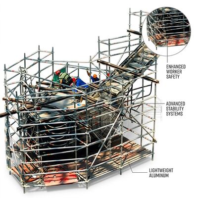
Step 1: Base Frame Positioning (0:00-1:30). Unfold the base frame assembly from its transport configuration and position the four castor wheels at the desired work location. Engage all four wheel brakes by depressing the brake pedal on each castor. The base frame's laser-etched alignment marks provide visual confirmation that the frame corners form a true rectangle within ±2mm diagonal tolerance—critical for ensuring vertical standards will seat correctly in subsequent steps. If the ground surface is uneven, deploy the integrated leveling screws at each corner, adjusting until the bubble level integrated into the base frame cross-member indicates within 0.5 degrees of horizontal in both axes.
Step 2: First Bay Vertical Standards (1:30-3:00). Insert the two first-bay vertical standards into the base frame corner sockets. Each standard seats with an audible metallic click as the spring-loaded retention pin engages the socket's capture groove. Verify the green indicator tab has deployed on both retention pins before proceeding. The standards are color-coded with a red band at the bottom end and blue band at the top, providing immediate visual orientation confirmation that prevents the common error of installing standards upside-down.
Step 3: Horizontal and Diagonal Braces (3:00-6:30). Beginning at the lowest rosette ring position, install the four horizontal braces and two diagonal braces that complete the first bay's structural triangulation. Each push-fit interlock connector is aligned above the desired rosette ring position and pushed firmly downward. The internal dual-cam locking mechanism produces an audible double-click—the first click indicates initial jaw engagement, the second confirms complete seating with the retention cam deployed behind the collar lip. The green visual indicator tab on each connector body provides supplementary confirmation visible from ground level without climbing. Complete all six connections for the first bay before proceeding. This sequence ensures three-dimensional rigidity before weight is applied to any single connection point.
Step 4: Platform Deck Installation (6:30-7:30). Position the first platform deck panel at the desired working height rosette ring position. Each deck panel features integrated hook brackets that engage the horizontal braces from above, requiring no separate fasteners. The panel's self-weight seats the hooks fully into their receiving channels. Confirm that all four hook brackets are fully engaged by visually verifying the red marking on each hook is no longer visible above the brace tube. Install the guardrail panels by inserting their stanchion pins into the vertical standard top sockets, completing the bay's fall protection system.
Step 5: Upper Bays and Final Platform (7:30-8:00+). Additional bays follow the identical sequence of standards, braces, and platform decks, working upward one bay at a time. The build-from-within methodology means all components for the next bay are passed up from the completed platform level below, with the installer never working from an unguarded position. The complete 8-meter tower, comprising four 2-meter bays, is fully erected and ready for access in under 8 minutes by a trained two-person crew.
Key Features| Parameter | Specification |
|---|---|
| Connection Type | Push-Fit Interlock (Tool-Free) |
| Connector Material | A356-T6 Investment Cast |
| Spring Material | 17-7 PH Stainless Steel |
| Platform Dimensions | 1.8m x 0.6m |
| Working Height Range | 2m - 12m |
| Material Grade | Aluminum Alloy 6082-T6 |
| Tube Diameter | 50.8mm |
| Tube Wall | 1.8mm |
| Assembly Time (8m) | Under 8 min (2 crew) |
| Load Capacity | 200 kg/sqm |
| Surface Treatment | Anodized Silver |
| Wheel | 200mm Lockable Castor |
| Standard | EN1004:2004 |
All interlock connectors pre-installed on brace ends, requiring zero field assembly. Includes release lever tool in dedicated base frame holster plus ten spare connector assemblies. Plywood case packaging with individual tube sleeves and connector protection caps. 24-month warranty covering complete system including connector mechanisms.