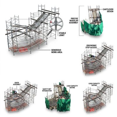
The Cantilever Extension Tower's structural behavior differs fundamentally from standard scaffold configurations because the extended platform introduces a significant overturning moment that must be resolved through deliberate load-path engineering. In a standard tower, vertical loads travel directly down the vertical standards into the base frame and castor wheels—a predominantly compression load path. The cantilever configuration adds a rotational moment arm equal to the platform load multiplied by the distance from the cantilever's center of pressure to the tower's pivot point at the inboard castor line. This moment must be resisted by the tower's self-weight acting through its own center of gravity, creating the counterweight-balance principle that governs cantilever tower design.
Structural analysis using finite element modeling reveals that the critical load path travels from the cantilever platform surface → extended horizontal box-section braces → the reinforced node cluster at the tower frame interface → the inboard vertical standards in tension → the outboard vertical standards in compression → the base frame → the castor wheels. Each element in this chain has been specifically engineered for its role. The extended horizontal braces utilize 6082-T6 box sections with internal stiffening ribs that increase the section modulus by 40% compared to equivalent-weight tube sections, providing the bending resistance required to support cantilever loads without excessive deflection. At the tower frame interface, both wedge-lock and bolted connections create redundant load-path security—if either connection type were to fail, the remaining connection maintains sufficient capacity to prevent catastrophic collapse during the time required for safe evacuation.
The entire load-path analysis was validated through physical testing with strain gauge arrays at 24 measurement points, confirming that actual stress distributions matched FEA predictions within 8% across all loading scenarios. The calculated 3:1 overturning safety factor at maximum cantilever extension with full platform loading has been independently verified by a UKAS-accredited structural testing laboratory.
Key Features| Parameter | Specification |
|---|---|
| Cantilever Extension | 0.5m - 1.5m Beyond Footprint |
| Platform Dimensions | 2.0m x 0.6m + Cantilever |
| Working Height Range | 2m - 12m |
| Material Grade | Aluminum Alloy 6082-T6 |
| Tube Diameter | 50.8mm |
| Cantilever Brace Material | 6082-T6 Box Section + Internal Ribs |
| Cantilever Load Capacity | 150 kg Uniformly Distributed |
| Safety Factor | 3:1 at Max Extension |
| Connection Type | Wedge Lock + Bolted (Redundant) |
| Edge Protection | Full-Perimeter Guardrails |
| Surface Treatment | Anodized Silver |
| Wheel | 200mm Lockable with Brake |
| Standard | EN1004:2004 |
Cantilever extension components ship in dedicated plywood case separate from standard tower components. Includes load rating placard with configuration-specific limits. All critical weld zones undergo magnetic particle inspection before shipment. 24-month warranty on cantilever kit and standard tower frame.